
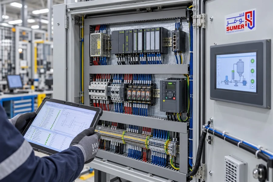
PLC panels are the control center in many machines and production lines; they receive sensor signals and operation commands, process them according to a specific program, and then send commands to motors, valves, contactors, and other system elements. However, the success of a control panel does not depend on the PLC device alone, but on the accuracy of the process study, component selection, power and control circuit design, and the quality of programming and testing.
This guide explains what a PLC panel is, its components, how it works, the data required before design, how to choose the control unit and the number of I/O points, and the stages of manufacturing, programming, and testing. It also explains the factors that determine the cost of executing the panel and the mistakes to avoid when creating a new panel or upgrading an existing one.
SUMER provides Delta PLCs and implements control solutions for machines and factories according to the requirements of each application. For an initial study, send the machine description, the I/O list, load capacities, and pictures of the current panel (if any) to the SUMER team.
What are PLC panels?
A PLC panel is an electrical control panel that contains a Programmable Logic Controller (PLC) along with the necessary protection, power supply, wiring, and operation components to control a machine or an industrial process. The panel acts as an organized link between field devices, such as sensors and switches, and loads, such as motors, valves, and alarms.
The panel may be small, controlling a single machine, or a larger system distributed across multiple panels, I/O stations, and communication networks. Therefore, there is no single fixed design suitable for all projects; each panel is built according to the sequence of operations, the number of signals, the nature of the loads, the factory environment, and the required safety level.
What is the difference between a PLC device and a PLC panel?
A PLC device is the control unit that executes the program, and it may include a CPU and built-in inputs and outputs, or connect to expansion modules. A PLC panel, on the other hand, is the integrated system that contains the control device along with the power supply, circuit breakers, relays, contactors, terminals, and communication means. It may also include an HMI screen, an inverter (VFD), or a servo drive depending on the application.
If you want to compare the configurations of the control units themselves, you can refer to the guide on the types of PLC devices and how to choose the right type. This article, however, focuses on the panel as a complete control system, from data collection to testing and commissioning.
How does a PLC control panel work?
The control cycle starts from the field devices. For example, a proximity sensor sends a signal to a digital input, or a pressure sensor sends an analog value to an Analog Input. The PLC reads these signals, executes the program logic, and then updates the outputs to trigger a relay, valve, or contactor, or sends a reference value to another device.
-
Signal Collection: Input modules receive the states of buttons, sensors, interlocks, and process measurements.
-
Processing: The CPU executes the operation conditions, timings, calculations, and the sequence of the process.
-
Sending Commands: Output modules transmit start, stop, and control commands to the appropriate components.
-
Display and Intervention: The HMI displays states, alarms, and values, and allows the operator to input authorized commands.
-
Feedback: Operation states, faults, and measurements return to the PLC to ensure a step is executed before moving to the next.
This cycle repeats rapidly during operation. However, machine safety should not rely on the program alone; emergency stop circuits and functional safety are designed using a safety architecture and components appropriate for the nature of the risks, by a qualified engineer, and cannot be replaced by a button on an HMI screen or by logic inside a standard PLC.
Core Components of a PLC Control Panel
The configuration of PLC panels varies from one project to another, but most industrial panels combine the following components:
1. Panel Enclosure and Protection Means The panel enclosure is selected based on the installation location, dust, moisture, temperature, component space, and cable entry method. The protection aspect usually includes a main circuit breaker or disconnect switch, branch breakers or fuses, and proper grounding, with power and control circuits separated and organized according to the design.
2. Control Circuit Power Supply Many PLCs, sensors, and operating screens run on 24V DC. Therefore, the consumption of all loads and inrush currents must be calculated, leaving an appropriate margin before selecting the supply. The 24V Power Supply Selection Guide for Control Panels helps you calculate current and power and review the most important selection criteria.
3. PLC Unit and I/O Modules The CPU handles program execution, while input modules receive signals and output modules send commands. I/O points may be built into a single unit or distributed across local or remote expansion modules. Selection depends on the number, type, speed, and required precision, not just the number of points.
4. Relays, Contactors, and Interfacing Means Interface relays are used when there is a need to isolate or adapt signals, while contactors handle switching power loads within a designed and protected circuit. Terminals, wire ducts, and wire/terminal numbers make connections clear and maintainable.
5. HMI Screen The operator interface allows monitoring of states, values, and alarms, as well as inputting operation commands. The screen design must be clear, sensitive settings and permissions must be restricted, and addresses and data must match the PLC program. SUMER provides Delta HMI screens; you can read the guide on programming HMI screens and linking them with PLCs to learn the integration steps between the two.
6. Inverter or Servo Drive If the machine requires changing the speed of an AC motor or controlling acceleration and deceleration, the system may include a VFD (Inverter). For applications requiring more precise control over position, speed, or torque, an appropriate servo drive and motor might be used. The application, mechanics, and required precision determine the most suitable solution.
7. Communication, Cooling, and Accessories The panel may include an industrial network switch or communication converters, fans or cooling units when necessary, internal lighting, service outlets, and temperature monitoring devices. Heat dissipation and panel ventilation must be calculated, and signal cables should be separated from power cables to reduce interference.
Where are PLC panels used?
A PLC panel is used when a process requires a logical sequence, monitoring of multiple states, changing operation settings, or data exchange between industrial devices. Common applications include:
-
Packaging, weighing, and dosing machines.
-
Conveyor belts, sorting, and assembly lines.
-
Pumping stations, water treatment, and tank systems.
-
Ovens, dryers, and temperature control systems.
-
Cutting, printing, and forming machines.
-
Production lines combining PLC, HMI, and an inverter or servo.
-
Upgrading old machines and replacing traditional controls or unsupported units.
The solution may be a standalone panel for a machine, a main panel connecting several parts, or a set of panels distributed across a production line. Distances, number of signals, response speed, and the communication network determine the best architecture for the project.
What data is required before designing a PLC panel?
The biggest difference between a panel executed quickly and one subjected to frequent modifications is the quality of data before starting the design. The clearer the requirements, the more accurate the component selection, cost, and timeline become.
Process Description and Sequence of Operation A Sequence of Operation must be written detailing start and stop conditions, cycle steps, transition conditions, Manual and Auto modes, and how to handle faults and recover operation. Drawings or videos help but do not replace an agreed-upon description of the required logic.
I/O List (Inputs and Outputs) The list includes every signal, its type, source, and function. A distinction must be made between DI, DO, AI, and AO, specifying the signal voltage, type, and range, such as 4–20mA or 0–10V when using analog signals:
-
Digital Input: Examples include buttons, Limit Switches, and proximity sensors. You must specify: Voltage, connection type, and normal signal state.
-
Digital Output: Examples include relays, valves, and indicator lights. You must specify: Output type, load current, and isolation method.
-
Analog Input: Examples include pressure, temperature, level, and flow sensors. You must specify: Signal range, precision, isolation, and calibration.
-
Analog Output: Examples include speed references or control valves. You must specify: Output range, load, and connection method.
-
High-Speed / Pulse: Examples include Encoders or position commands. You must specify: Frequency, signal type, and motion requirements.
Load List and Power Source The power, voltage, and current of each motor, heater, valve, and load must be determined, along with its operation method, number of starts, and loads operating simultaneously. Available power sources and network conditions are also specified, as the design of power and protection circuits relies on this data.
Communication and Operator Interface You must specify the devices that will exchange data and the required protocols, such as Modbus RTU or Modbus TCP depending on what the actual devices support, as well as the required screens, Recipes, alarms, reports, and user levels on the HMI.
Operating Environment and Expansion Temperature, humidity, dust, vibration, panel location, distances, and cable entry methods affect the design. It is beneficial to determine expected expansions and the number of spare points instead of discovering a lack of space or capacity after commissioning.
How to choose the right PLC device for the panel
A PLC is not chosen solely by its brand or the number of points. The comparison starts with the process requirements and then reviews the following points:
-
Number and Type of I/O: Total current and spare points, separating digital, analog, and high-speed points.
-
Output Type: Relay or Transistor based on switching speed, load, and connection method.
-
High-Speed Functions: High-speed counters, Pulse Output, or motion requirements.
-
Communication: Ports and protocols required for the HMI, inverter, and other devices.
-
Program Capacity and Performance: Size of logic and data, and required scan cycle speed.
-
Expansion: Ability to add I/O, communication modules, or specialized functions.
-
Maintenance and Availability: Ease of obtaining spare parts, software, backups, and support.
For example, the Delta DVP32ES200T offers 32 built-in I/O points, including 16 digital inputs and 16 Transistor outputs, with communication features and pulse functions detailed on the product page. This does not automatically make it the right choice; its features must be matched against the project's signal list, speed, and functions.
In applications requiring built-in Ethernet connectivity, the Delta DVP12SE11R can be considered after reviewing the number of points, protocols, and other required specifications. The final decision is based on the datasheet and design, not the series name alone.
Stages of Designing and Executing a PLC Panel
-
Site and Process Study: Understanding the machine cycle, risks, loads, and existing devices.
-
Fixing Requirements: Approving the Sequence of Operation, I/O list, functions, and scope of work.
-
Electrical Design: Preparing power, control, and wiring diagrams, and the bill of materials.
-
Sizing and Layout: Determining the panel enclosure, component arrangement, cable routing, ventilation, and spare space.
-
Assembly and Wiring: Installing components, routing wires, numbering, and grounding according to the drawings.
-
PLC and HMI Programming: Building the sequence, interlocks, alarms, screens, and user permissions.
-
Review and Testing: Checking connections, signals, and functions, and conducting a documented FAT before shipping.
-
Site Installation and Commissioning: Connecting field devices, performing SAT tests, and fine-tuning the process.
-
Handover: Delivering drawings, programs, backups, signal lists, and operation and maintenance manuals.
If the project includes manufacturing a complete panel, check the Electrical Control Panel Design and Manufacturing Service to see the general overview of panel services, while this guide helps in preparing the specific requirements for the PLC system.
What should be tested in FAT before delivering a PLC panel?
A Factory Acceptance Test (FAT) reduces commissioning surprises on-site. Its scope depends on the project but may include the following items:
-
Visual Inspection: Reviewing component arrangement, numbering, wiring quality, separation between routes, and grounding.
-
Schematic Review: Ensuring components, connections, and terminal numbers match the drawings.
-
Power Supply Test: Checking voltages, polarity, branch distribution, and protection before turning on devices.
-
I/O Check: Simulating each input and verifying the correct output, address, and proper naming.
-
Sequence of Operation: Testing Auto and Manual modes, interlocks, timings, and stop/recovery states.
-
Alarms: Verifying the correct alarm appears, is logged, and checking the method of acknowledgment and clearing the cause.
-
Communications: Testing data exchange with the HMI, drives, and other devices, as well as communication loss scenarios.
-
Backups: Saving the final versions of programs, settings, and drawings.
FAT cannot always fully simulate the real load and mechanical conditions entirely, so it is followed by a Site Acceptance Test (SAT) and trial runs. It is best to define the acceptance criteria, who attends the test, and what will be simulated before manufacturing begins.
Common Mistakes When Designing PLC Panels
-
Starting programming without an approved sequence of operations: Leads to frequent modifications and mismatched expectations.
-
Calculating I/O by count only: The available points might be of the wrong type or lack high-speed functions.
-
Not leaving logical spares: Makes adding a sensor or function later difficult.
-
Overcrowding the panel: Raises temperatures and complicates maintenance and expansion.
-
Mixing power and signal cables: Can increase interference and affect readings and communication.
-
Neglecting numbering and documentation: Turns any simple fault into longer downtime.
-
Relying on the HMI as a safety element: The screen is for operation and display, not a substitute for a proper safety circuit.
-
Failing to test failure states: You must study the loss of a sensor, connection, or power supply, and how the system will transition to a safe state.
-
Delivering the panel without source files: Hinders future maintenance and modifications.
When do you need to upgrade an old PLC panel?
An upgrade may be appropriate when breakdowns become frequent, the PLC or HMI becomes obsolete/unavailable, there is no backup of the program, or the machine requires new functions and communications. However, retrofitting is not merely transferring wires from one device to another; signal types, addresses, outputs, protocols, and operating voltages may differ.
The Retrofit process begins with inventorying components, mapping existing wiring, and securing available backups. Next comes understanding the actual operating logic and preparing a conversion and testing plan. It is best to execute the transition during planned downtime, with a rollback plan and required spare parts to minimize production loss.
PLC Panel Maintenance and Troubleshooting
Preventive maintenance does not mean changing the PLC periodically; it means maintaining a stable operating environment and detecting issues before a breakdown. Reviews according to the factory's plan and component instructions include:
-
Checking temperature, ventilation, filter cleanliness, and fan conditions.
-
Reviewing voltages and the 24V DC source under operating conditions.
-
Checking for signs of overheating, discoloration, or abnormal odors.
-
Reviewing terminals and connections following safe procedures and proper torque instructions.
-
Monitoring the alarm log and recurring faults instead of clearing them without analysis.
-
Keeping a dated backup of PLC and HMI programs, as well as settings for communication devices and drives.
-
Documenting any modification in the drawings, I/O list, and program.
When a fault occurs, diagnosis starts with symptoms, power, LED states, and alarms, then tracking the signal path from the sensor to the input and from the program logic to the output and load. The PLC is not replaced before verifying the power supply, wiring, and external devices. Measuring and intervening inside the panel must be done by a qualified person applying isolation and safety procedures.
What factors determine the cost of a PLC panel?
There is no fixed price for all panels because the cost relates to the project's scope and technical data. The most important factors include:
-
Number and type of I/O points, and the presence of Analog, High-Speed signals, or special modules.
-
PLC category, program capacity, communications, and expansion modules.
-
Number and capacities of loads, breakers, contactors, and protection devices.
-
Presence of HMI, inverter, servo, or industrial network.
-
Panel enclosure size, IP rating, cooling, and operating environment.
-
Complexity of the Sequence of Operation, programming, screens, recipes, and reports.
-
Site work, cabling, installation, testing, and commissioning.
-
Documentation, training, spare parts, and required post-delivery support.
To get a comparable quotation, ask suppliers to quote on the exact same scope of work, Bill of Materials, documents, and specific tests. The lowest price isn't actually the lowest if it excludes programming, commissioning, drawings, or the support the project needs.
Executing PLC Panels with SUMER
SUMER helps factories and machine builders select Delta components and prepare control and integration solutions between the PLC, HMI, inverter, or servo according to the application requirements. The study begins with the required process, not by picking a random model, and then reviews the signals, loads, communication, and expansion space before approving the solution.
To speed up the study and quotation process, send: a brief machine description, Sequence of Operation, I/O list, motor/load capacities, supply voltage, required HMI type and communications, and photos and diagrams of the current panel if available. Contact SUMER now to request a PLC panel study.